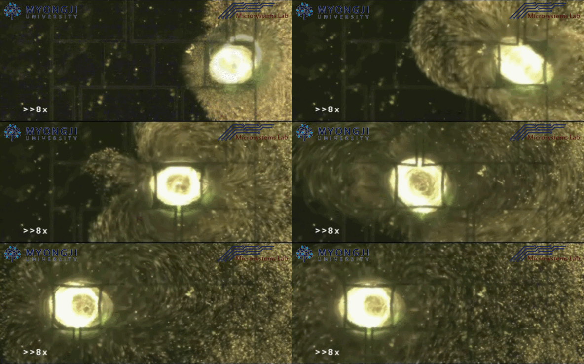

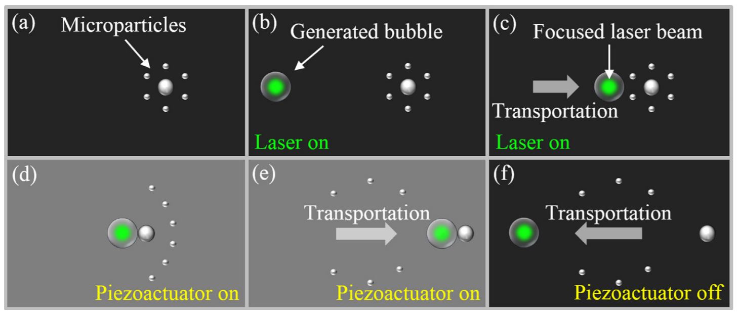
Schematic diagram of manipulation of microparticles with two different sizes by utilizing an optothermally and acoustically excited bubble on-demand. (a) Dispersed microparticles with different sizes. (b) Generation of a bubble through optothermal effects. (c) Transportation of the bubble toward the dispersed microparticles by using optothermocapillary effects. (d) Sorting and capturing of target particles with a specific size by means of acoustic radiation effects. (e) Transportation of captured particles through both optothermocapillary and acoustic radiation effects. (f) Releasing captured particles in the absence of acoustic agitation and subsequent return to the original position by way of optothermocapillary effects.
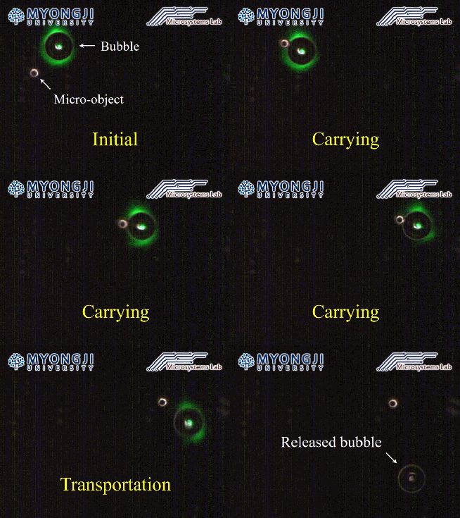
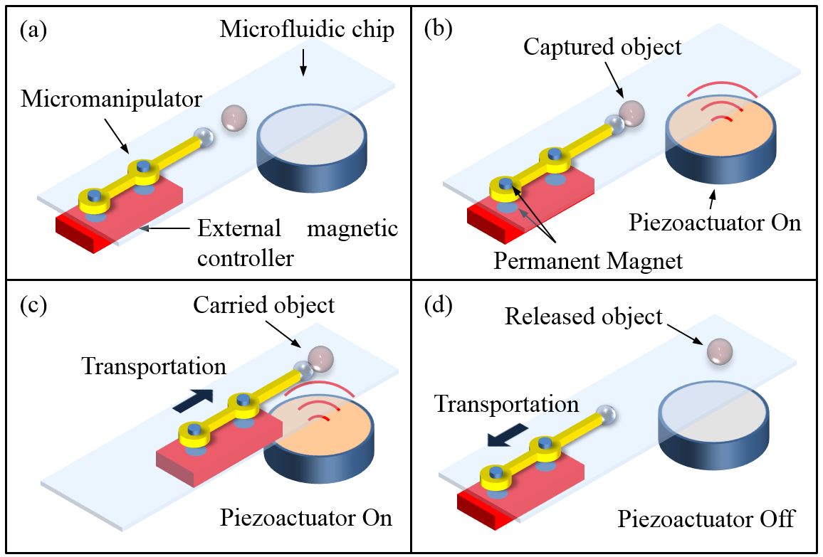
Schematic diagram of a proposed electromagnetically driven on-chip micromanipulator: When a bubble on the tip of the micromanipulator is acoustically excited at its natural frequency by a piezoactuator attached beneath the chip, it oscillates and simultaneously generates a radiation force, called a Bjerknes force, which results in pulling a neighboring object onto its surface, as shown in Fig. 1(b). The captured object can be transported to any location with the micromanipulator actuated by an external magnetic controller consisting of precisely controllable 2D traverse and twin permanent magnets (Fig. 1(c)). When the object carried with the micromanipulator reaches a target location, it can be released from the bubble simply by turning the piezoactuator off and transporting the micromanipulator to the original position, as shown in Fig. 1(d).

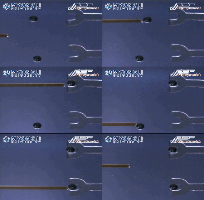
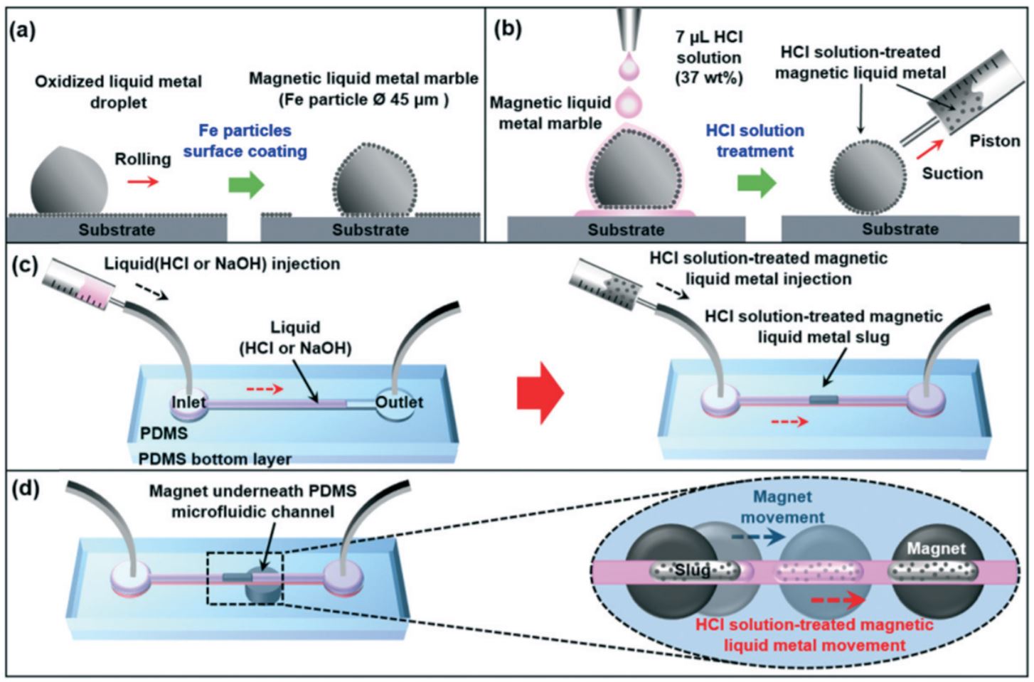
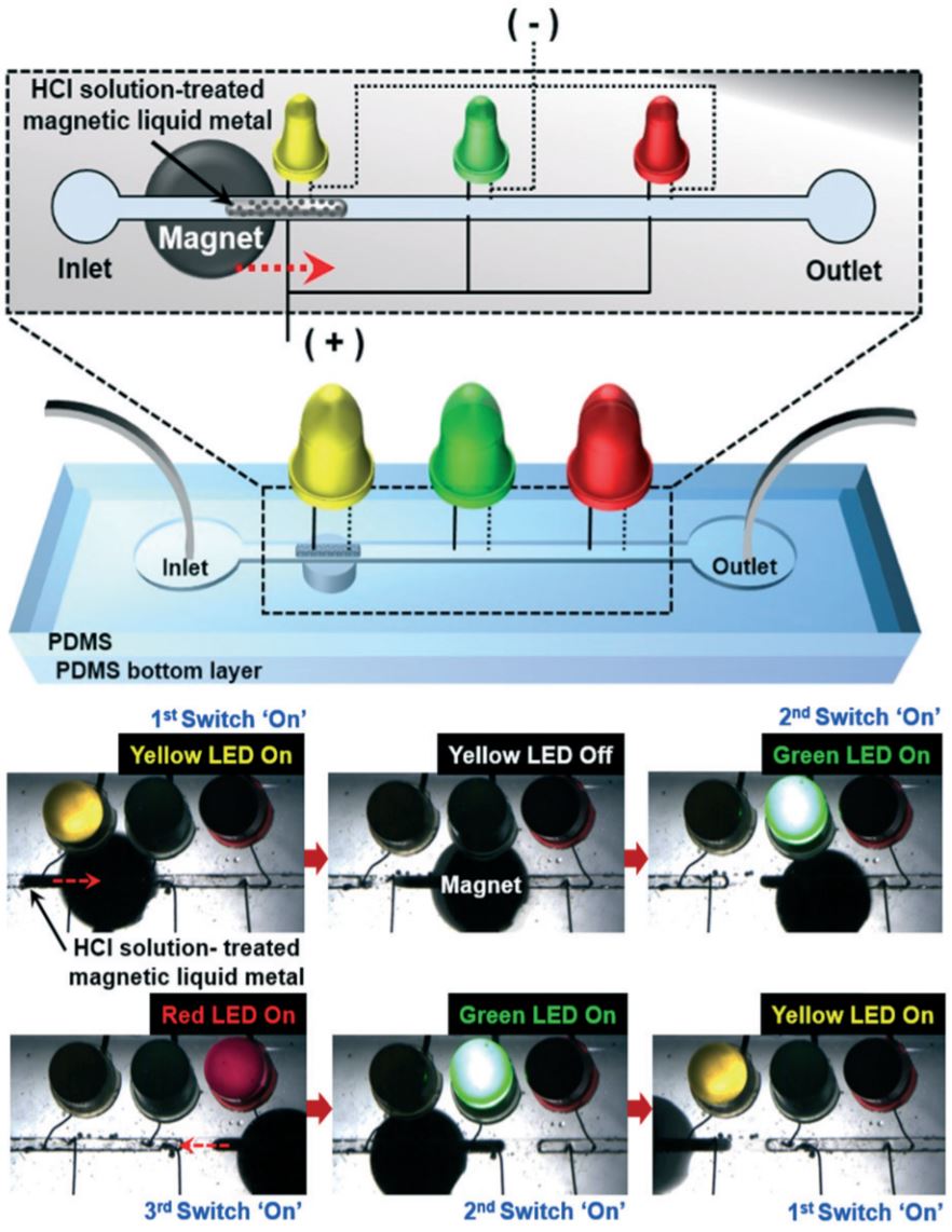
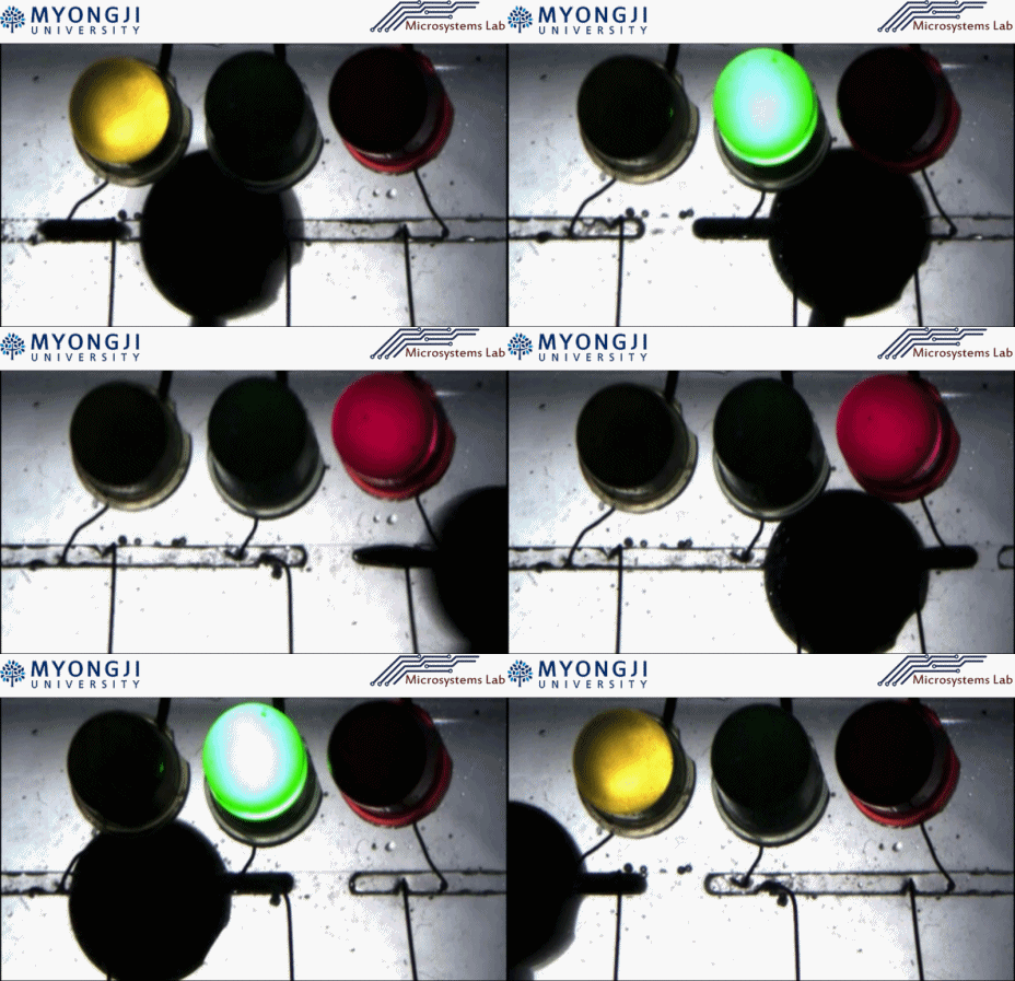
Conceptual schematic of the microfluidic-based magnetic-field-driven manipulation of the liquid metal: (a) coating with Fe particles, (b) HCl treatment and suction of the liquid metal, (c) HCl-treated liquid metal injection into the PDMS-based microfluidic channel filled with HCl or NaOH, and (d) on-demand magnetic manipulation of the HCl-treated liquid metal.

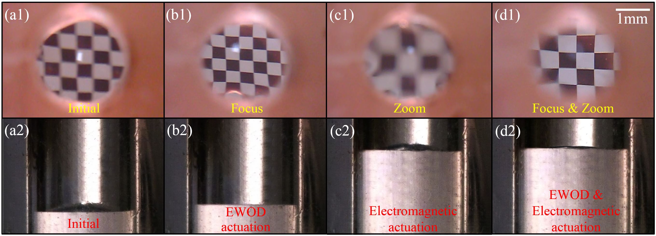
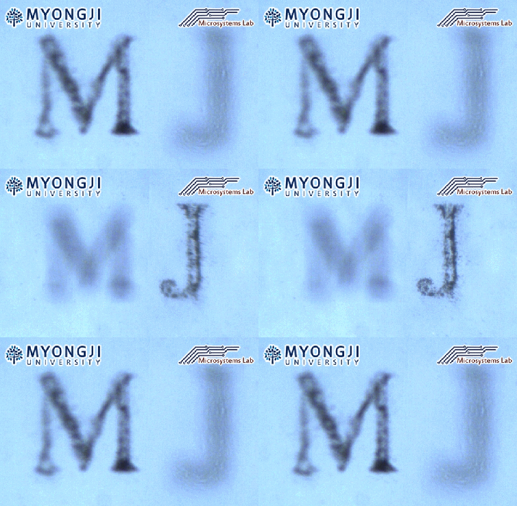
Multifunctional liquid lens (MLL) for miniature cameras used in smart devices and biomedical imaging systems has been developed in Myongji University Microsystems Laboratory. MLL firstly offers variable-focus and variable-zoom in a single lens system using two different actuation schemes : electrowetting-on-dielectric (EWOD) actuation for controlling the lens curvature and electromagnetic actuation for controlling the lens position.
Schematic diagram of a tunable liquid lens operated by electromagnetic actuation. According to Faraday’s law of electromagnetic induction, when electric current flows in an electric coil, a magnetic field is generated in its surroundings. The magnetic field is used to actuate or pull a ring-shaped neodymium magnet placed on the top of an elastic polydimethylsiloxane (PDMS) membrane in the liquid lens, resulting that the liquid inside an actuation chamber flows into the lens chamber through open walls. It brings the change of the surface profile and focal length of the liquid lens.
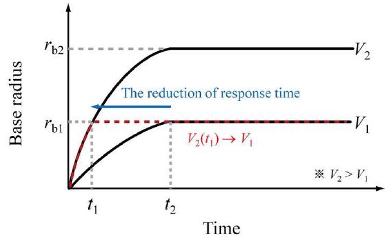
Conceptual description of the enhancement of electrowetting-on-dielectric (EWOD) response speed based on overdrive method. To improve response time (time to reach base radius (rb1), an overdrive voltage (V2) exceeding the target voltage (V1) is initially applied for the first frame (t1), and the target voltage (V1) is then applied for subsequent frames. This results in a reduction of the response time (t2-t1).
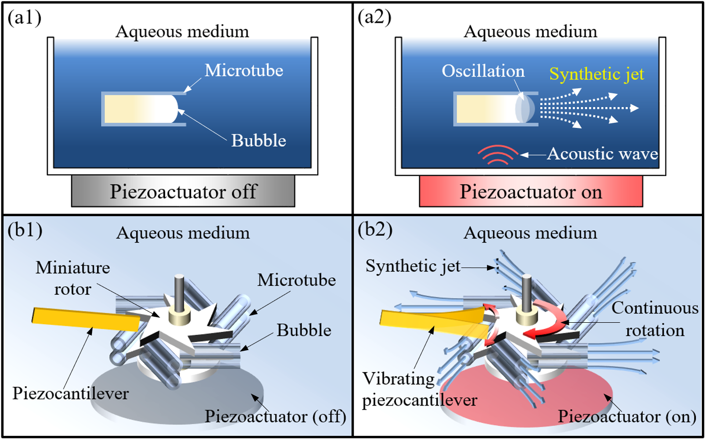
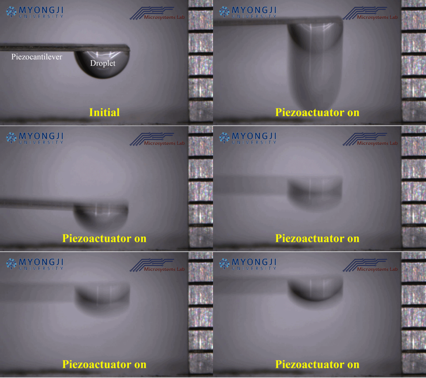
An acoustically oscillating droplet induced motion-powered energy harvester: (a) When a water droplet is acoustically excited by a piezoactuator around its natural frequency, it oscillates; (b) When an acoustically oscillating droplet is placed on the tip end of a piezocantilever, the oscillating motion of the droplet induces the continuous bending of the piezocantilever as the reaction, resulting in electric power generation from the piezocantilever. The envisioned energy harvesting system can extract mechanical power from acoustic noise over a wide range of frequencies using liquid droplets with different sizes and natural frequencies and convert the mechanical power to electrical power for wireless electronic devices. This new type of actuation technique is a simple but useful tool not only for energy harvesting systems but also for potential acoustic wave sensors and actuators in the future.
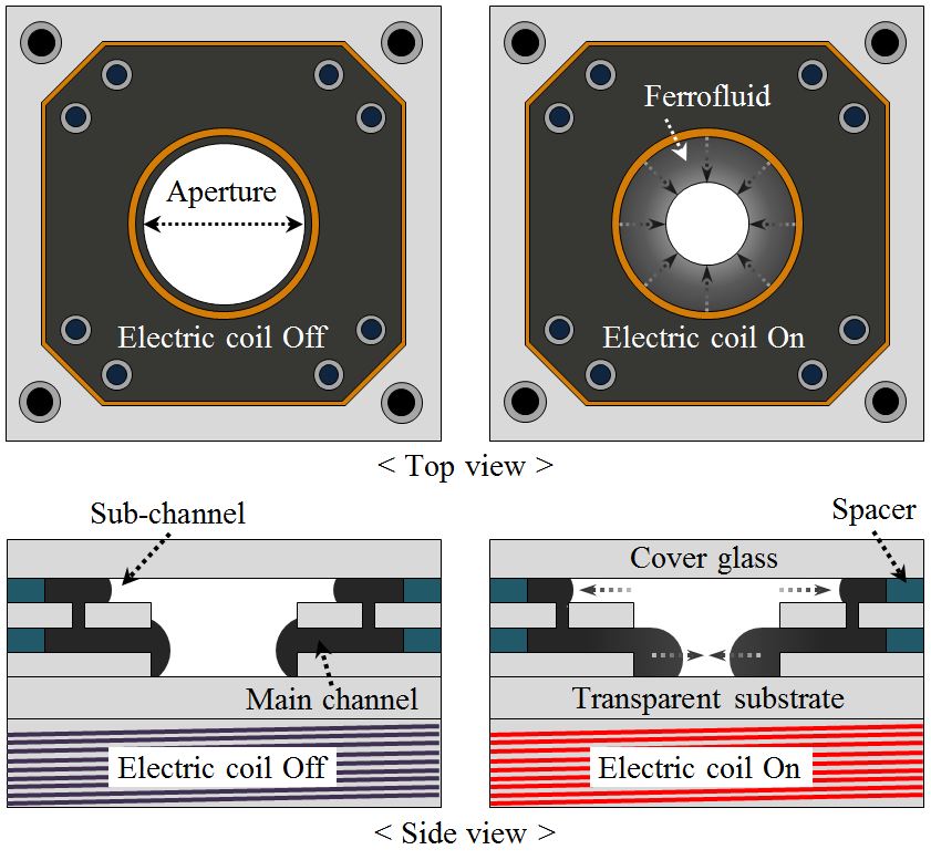
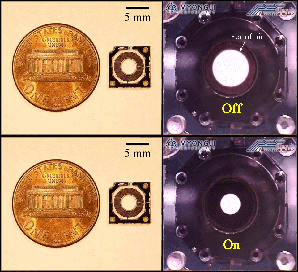
Schematic diagram of a tunable optical iris operated by electromagnetic actuation: When an electrical current is applied to an electric coil, a ferrofluid initially filled inside the sub-channel of the iris is electromagnetically actuated and pulled to the center of the main channel, resulting in changing the aperture of the iris.
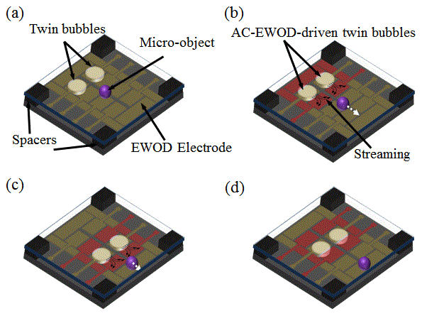
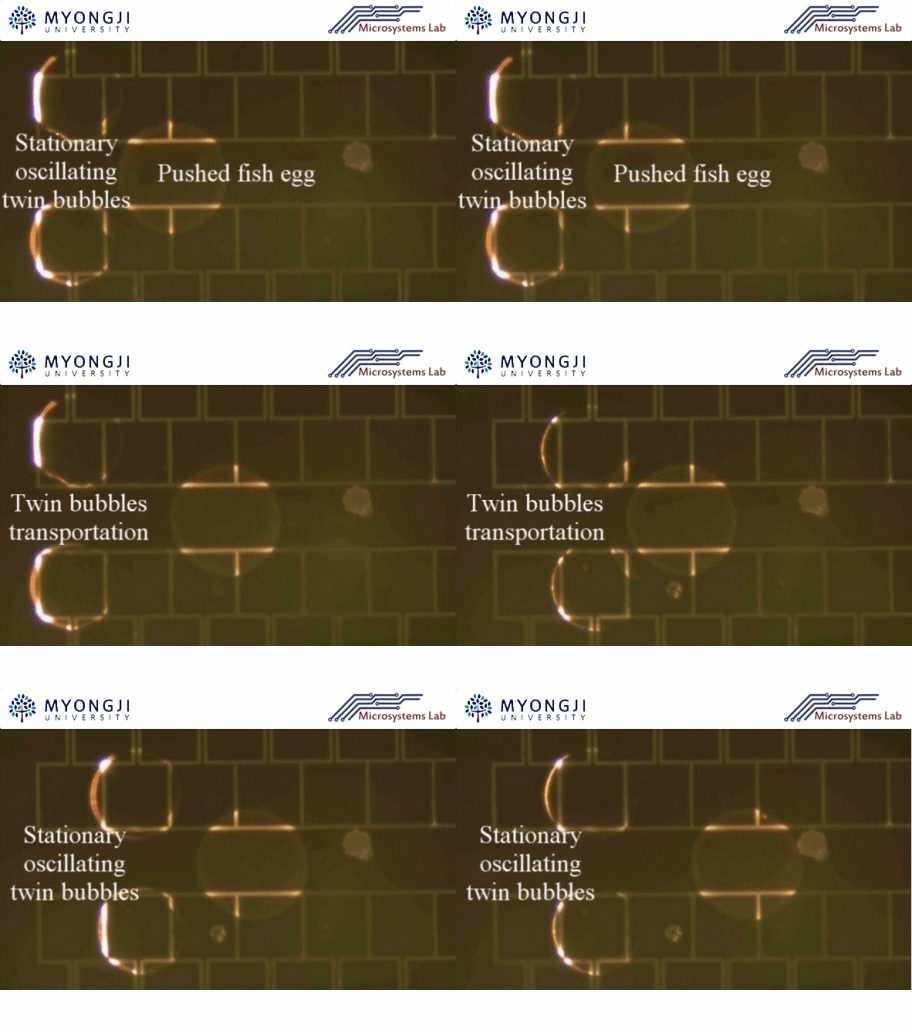
Micro-object manipulation by AC-EWOD-driven twin bubbles: (a) Initial state; (b) When twin bubbles actuated by AC-EWOD at a certain frequency (100 Hz) generate streaming, a micro-object is pushed by the streaming and transported to the next EWOD electrodes; (c) The object is carried by the sequential AC-EWOD operations with the twin bubbles to the right end of EWOD electrodes; (d) When the twin bubbles actuated by AC-EWOD at 1 Hz are transported to the original position without streaming, the object is released from the bubbles and remains where it is. Note that the bubble-induced streaming is generated only at a certain frequency.
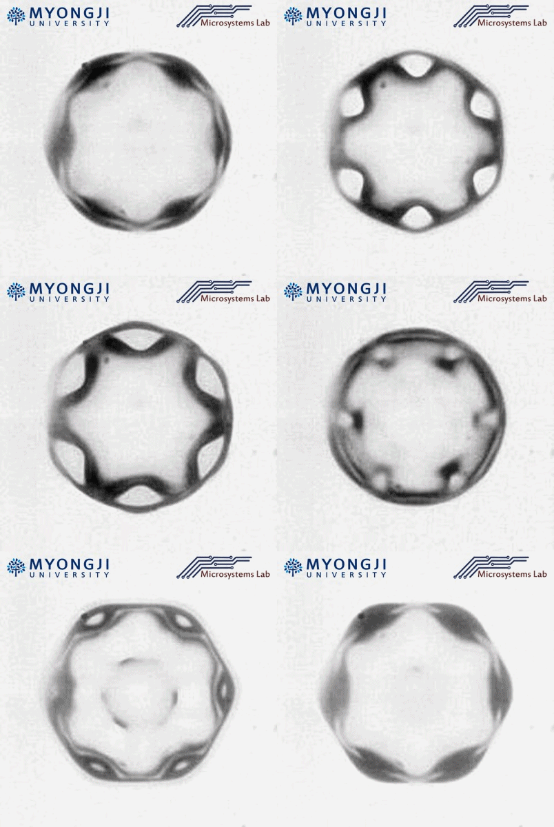
Schematic of an envisioned microfluidic mixing system using an alternating current electrowetting-on-dielectric (AC-EWOD)- driven mobile oscillating bubble: (a) Initial state; (b) When a voltage is applied to the top ground electrode and the bottom electrodes where a bubble sits, the bubble oscillates and simultaneously generates a microstreaming flow. Neighboring microparticles are stirred and mixed by the flow; (c) When the oscillating bubble is transported to the right by sequentially activating the array of EWOD electrodes, the microstreaming flow from the bubble is stirring and mixing microparticles through the entire microfluidic chip; (d) the initially gathered microparticles in the left side are widely spread over the entire area in the microfluidic chip.
